


January 05, 2026
How to Achieve 15-Day Grid Connection for Utility ESS Projects
Share my #SolaXStory


As large-scale battery energy storage systems (BESS) become more common, safety concerns have escalated into a critical issue. With increasing project sizes, power densities, and the deployment of systems in diverse and challenging environments, the focus on safety has intensified.
While concerns persist, data-driven analysis by groups like Camelot Energy shows the BESS failure rate has stabilized at approximately 0.3%, a risk profile equivalent to that of a standard American household fire, validating the success of modern layered safety protocols(The Camelot Energy Group: Putting BESS Fires in Everyday Context).
This guide explains these three essential layers from an engineering perspective, detailing the purpose of each layer, identifying potential failure modes, and describing the methods necessary to validate their efficacy.
Furthermore, we will explicitly map where the conceptual considerations of trene liquid and ess trene—which form the technical foundation of systems like the ESS-TRENE Liquid Cooling System—fit within a comprehensive utility safety program, particularly regarding critical thermal strategy and system architecture choices.

Core Foundations of Utility BESS Safety
The Hazard Chain: From Single Fault to Propagation Event
Most catastrophic incidents in Battery Energy Storage Systems (BESS) result from a series of failures, rather than a single fault. Typically, a thermal or electrical failure initiates internal cell heating, which leads to the venting of hot gases and decomposition products from the electrolyte. If the heat transfer to neighboring cells exceeds their thermal tolerance, the failure can spread. If these vented gases accumulate faster than ventilation systems can handle, ignition is possible, potentially leading to jet flames or severe deflagration.
The layered safety model addresses this risk by targeting different points along the hazard chain. Prevention reduces the chance of failure and slows propagation, detection reduces the time to trigger a safe response, and mitigation contains the consequences, focusing on controlling heat, fire, and pressure.
Codes in Practice: Thresholds, MAQs, and Compliance Challenges
In large utility projects, compliance with codes significantly influences design decisions. For example, the U.S. International Fire Code (IFC) defines a Maximum Allowable Quantity (MAQ) of 600 kWh for lithium-ion systems within a single fire area. This becomes a critical constraint for large-scale installations, which may need to implement additional testing, documentation, and mitigation systems to ensure safety and code compliance if they exceed these thresholds.
Standards: The Role of UL 9540 and UL 9540A
Regulatory authorities are increasingly moving beyond generic compliance, demanding robust data to address fire and explosion hazards in battery energy storage systems (BESS). The 2025 fifth edition of UL 9540A, released in March, reflects this shift by refining testing methodologies based on real-world incident insights(An inside look at the updates to UL 9540A: 2025). When tightly packed electrochemical energy, complex power electronics, and structural constraints converge, a minor fault can rapidly escalate into thermal runaway, leading to fires and hazardous gas leaks.
Testing Mindset: Evidence, Assumptions, and Configuration Control
A key safety challenge is ensuring that test results reflect the actual system configuration. Any changes to system components after testing, such as modifying vents or BMS settings, can compromise safety. Proper configuration control is essential, ensuring that any engineering modifications are tracked and safety standards are adhered to throughout the project lifecycle.
Layer 1 Prevention: Thermal Management and Design Controls
The primary goal of the prevention layer is to substantially reduce the frequency with which a “bad event” might occur. In utility-scale systems, prevention extends far beyond simply selecting a safe cell chemistry. It is achieved through a deliberate combination of electrochemical choices, robust mechanical architecture, and advanced controls designed to maintain the system strictly within a known-safe operating envelope. Prevention aims to lower the likelihood of an initial fault and significantly reduce the potential for a localized incident to propagate.
This is where the principles of SolaX’s ESS-TRENE Liquid Cooling technology are paramount. The concept of trene liquid serves as a shorthand for the thermal management strategy—specifically, liquid-based heat transfer approaches that are highly effective at stabilizing cell temperatures and reducing problematic localized hot spots. In prevention terms, a well-designed liquid coolant strategy is essential because it effectively reduces temperature gradients. These gradients are often the silent driver behind non-uniform aging, increased impedance, and the localized overheating that can trigger thermal events.
While the ESS-TRENE Liquid Cooling System offers superior temperature uniformity and heat rejection, any liquid strategy still requires comprehensive assessment. This assessment must cover potential leak risk, the dielectric properties of the coolant (if applicable), necessary maintenance protocols, and a thorough evaluation of how the system behaves under exposure to fire.
Prevention is further strengthened by stringent operational rules. This includes comprehensive commissioning checks, strict adherence to firmware governance protocols, and the execution of periodic health diagnostics to ensure the system’s protective barriers remain intact. Treating thermal strategy only as a performance feature, rather than a crucial safety control, is a common pitfall to avoid.
Layer 2 Detection: Early Warning and System Architecture
If Layer 1 Prevention successfully reduces the occurrence of abnormalities, Layer 2 Detection’s goal is to minimize the duration abnormalities persist before corrective action is taken. Effective detection buys crucial time. It involves identifying precursors to failure, such as abnormal temperature rise rates, unexpected voltage divergence, shifts in insulation resistance, or early-stage off-gassing. Detecting these early signs allows for a controlled shutdown and the isolation of the compromised section before the incident escalates.
Modern large-scale detection systems must be sophisticated, typically combining multiple signals:
Heat and temperature sensing to detect abnormal rise rates.
Off-gas or gas concentration sensing to identify decomposition products.
Electrical anomaly detection for identifying rapid imbalances or insulation failures.
This multi-signal approach is directly related to the concept of ess trene—the system architecture. Ess trene represents the broader system structure that dictates how these disparate detection signals are aggregated, escalated, and acted on. The actual effectiveness of the sensor hardware relies entirely on whether the system architecture supports rapid isolation, clear alarm prioritization, and automated response sequencing. This integrated and coordinated response capability is key to managing vast arrays typical of utility BESS sites. A critical detection best practice is to define response time objectives, such as “from critical temperature rise to dispatch stop within Y seconds”.
Layer 3 Mitigation: Containment and Response
Mitigation is the contingency layer; it assumes that the Prevention and Detection layers may ultimately be breached. When thermal runaway, venting, or ignition occurs, mitigation is focused on strictly limiting consequences to personnel, property, and continuity of service.
Mitigation begins with compartmentation. Due to the inherent risk of large-scale BESS, fire barriers and separation strategies must be employed to ensure an event confined to one cabinet or container does not become a site-wide incident. Equally important is gas and pressure management. Effective ventilation is critical not only for maintaining optimal cooling during normal operation but also for preventing the accumulation of flammable gases released during a thermal event.
The choice of thermal strategy, referenced as trene liquid, also affects mitigation effectiveness. Since liquid thermal management changes the pathways of heat transfer and potentially the overall thermal mass of the system, it influences how heat might spread during an abnormal event. Therefore, the trene liquid strategy should be thoroughly evaluated as an integral part of the mitigation plan, not just as a performance optimization feature.
Safety Validation (Testing and Acceptance)
Safety layers are fundamentally dependent on validation to establish credibility. For large-scale utility systems, validation is a complex undertaking, typically involving a mix of component certification, overall system certification, and specialized fire propagation behavior testing.
At the project level, a practical safety acceptance program must include three key phases:
Verification that the installed configuration precisely matches the configuration certified or tested.
Functional testing of all alarms, escalation logic, and shutdown actions.
Validation of ventilation and pressure management performance under designed conditions.
Monitoring and Dispatch: Ensuring Operational Safety
Operational safety acts as the crucial link between the initial design intent and the real-world performance of the BESS on the utility site. For multi-unit utility deployments, fleet-scale visibility is not just a convenience; it is a fundamental safety control.
A strong monitoring program must achieve three key outcomes: Early detection at scale (identifying subtle trends across many units), Fast response workflows (enabling swift remote actions), and strict Operational discipline.
When utility systems participate in grid services, they are subject to potentially aggressive operation during peak events. Safe dispatching therefore mandates that constraints such as thermal derates, State of Charge (SOC) windows, and fault-based lockouts are seamlessly integrated into the control signals. Operational safety is maximized when monitoring, the Energy Management System (EMS), and dispatch control are designed and optimized together—a hallmark of the ess trene architectural philosophy—rather than being separately developed and bolted on after the fact.
Utility-Scale Selection and Decision Guide
Strategy Alignment: Utility BESS Design
Rapid deployment is increasingly supported by favorable economics. According to IRENA, the total installed cost of battery energy storage systems (BESS) has plummeted by 93% since 2010, reaching a global weighted average of $192/kWh in 2024. This cost efficiency allows developers to invest more heavily in the 'defense-in-depth' safety layers—prevention, detection, and mitigation—without compromising project ROI(IRENA: Renewable power generation costs in 2024).
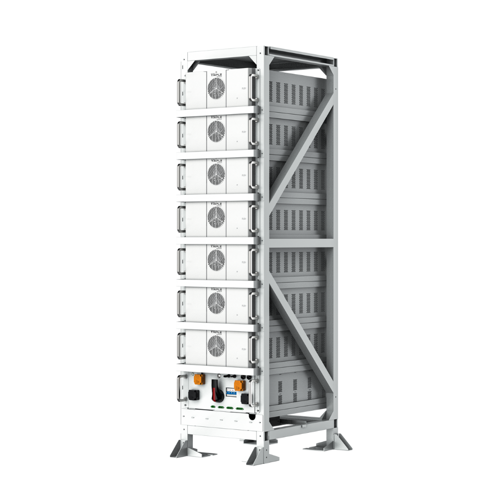
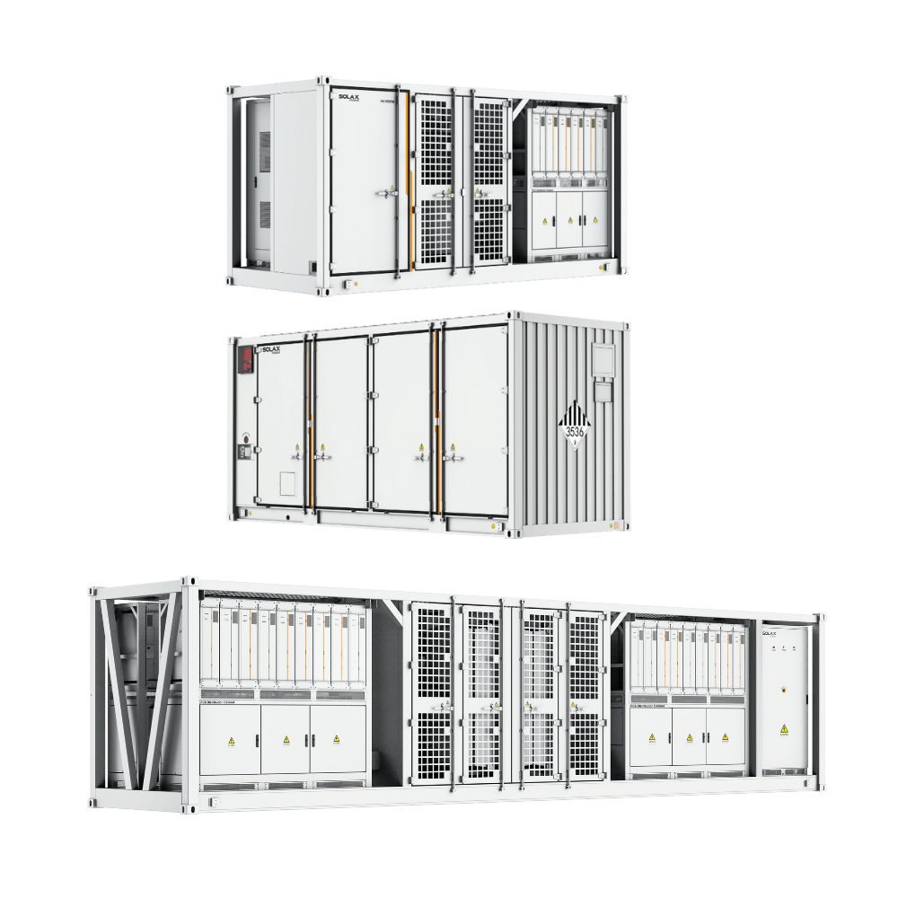
The initial selection process must begin by establishing the context: outdoor installation, local climate extremes, and proximity to sensitive exposures. For the SolaX Utility-Scale Solution ORI, design decisions must prioritize configurations that have strong evidence—such as robust UL 9540A data—for controlled propagation behavior, especially in constrained areas.
Scenario | Primary risk driver | Design focus | Operational focus | Trade-offs |
Utility-scale outdoor field | Multi-unit propagation and response logistics | Unit-to-unit separation, barriers, and access lanes | Fleet analytics, automated derates, and remote response playbooks | Requires larger land area; high emphasis on precise site layout |
Practical Decision Principles
Verify Certification Scope and Test Evidence: Owners must ask precisely what the certification and test reports actually cover. If the project deviates from the tested arrangement, clear engineering justification or additional testing may be required.
Align Detection and Suppression: Detection should be specifically chosen based on the hazard chain that presents the dominant risk. For large utility projects, the optimal solution is almost always multi-signal detection coupled with a clearly defined escalation ladder that rapidly triggers isolation and shutdown.
Ensure Operable and Auditable Controls: The system must provide granular alarms, historical event logs, and remote command capabilities. The control architecture must be validated to support conservative “safe states” even under conditions of communications loss or partial failures.
Best Practices & Common Pitfalls
Best Practices for Utility Deployment Safety
Mandate UL 9540 and UL 9540A Evidence Early: Treat the UL 9540A report as a foundational engineering input rather than merely a permit attachment. Ensure the final physical build rem ains entirely representative of the tested configuration.
Design Layered Alarms: Use deterministic actions linked to alarms. Employ rate-of-change logic where appropriate, as static absolute thresholds can frequently miss fast-developing anomalies.
Implement Robust Remote Monitoring: Ensure the deployment includes remote monitoring capabilities, detailed event logs, and a protocol for periodic safety review. Use this review process to adjust thresholds and maintenance schedules, guaranteeing that safety layers improve over time rather than slowly degrade.
Train for Escalation: Operators must be trained to practice not only normal operation but also how to respond when alarms conflict, sensors fail, and when a unit struggles to clear a fault.
Common Pitfalls to Avoid in Utility Projects
Ignoring Gas Hazards: Never assume that an “outdoor” setting automatically equates to safety. Gas behavior must always be evaluated as an integral part of the mitigation strategy, even in open-air installations.
Assuming Compliance without Verification: A critical pitfall is assuming compliance without verifying the scope and configuration control of the installed system. Changes that deviate from testing must be rigorously documented and re-evaluated.
Ambiguous Incident Workflows: Incident workflows should never be delayed due to ambiguous alarms. Design alarm hierarchies to ensure that “act now” critical alarms are rare but fundamentally unambiguous.
Mistaking Thermal Strategy: Avoid treating thermal management (i.e., trene liquid strategy) solely as a performance feature. It must be critically evaluated through the comprehensive prevention-detection-mitigation lens, recognizing its profound impact on safety, not just efficiency.
Conclusion
The shift toward massive infrastructure is clear: utility-scale projects dominated the market in 2025, representing 82% of all new capacity additions(Wood Mackenzie: Global energy storage market surpasses 100 GW in 2025).
Large-scale BESS safety is fundamentally an exercise in system management, not reliance on a single feature. When project developers, utilizing robust systems like the SolaX Utility-Scale Solution ORI, intentionally build prevention, detection, and mitigation into the design—and subsequently validate these layers with credible testing and operate them with disciplined monitoring—they effectively reduce both the probability and consequences of worst-case events.
The most reliable utility projects treat safety evidence, operational procedures, and configuration controls as core engineering deliverables. By applying the trene liquid (thermal strategy) and ess trene (system architecture) concepts to keep all three safety layers aligned, installers can achieve a safer, more defensible, and highly operable battery installation.
FAQ
Table of Contents
Latest News
Explore expert insights, practical guides, and the latest news on SolaX Power.


To the Latest Newsletter
Stay Ahead with the Latest SolaX Updates!
Subscribe
I have read and agree to Privacy Policy and User Terms