


Introduction
Keeping a commercial site running through grid instability is no longer just a “nice-to-have”—it’s a resilience requirement. In December 2025, more C&I operators are pairing on-site generation with energy storage to protect operations, reduce demand charges, and keep critical loads online during outages. If you’re evaluating TRENE liquid cooling for a containerized energy storage system, the goal is simple: build a backup-power setup that is predictable under stress, safe to operate, and easy to monitor.
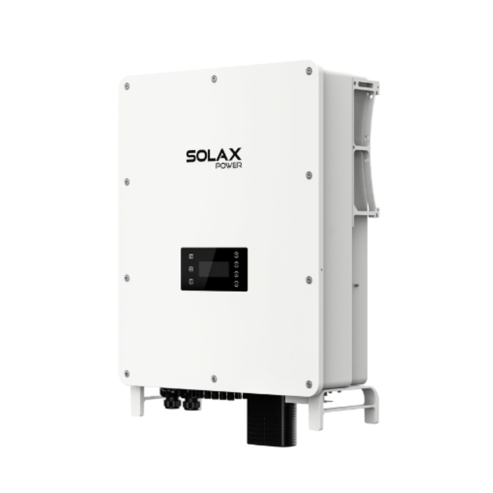
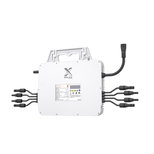
This how-to guide walks you through practical, step-by-step actions to plan, configure, and validate a commercial backup-power system built around SolaX Power’s liquid-cooled ESS TRENE system. You’ll learn how to size critical loads, choose an operating strategy, set commissioning checks, prepare safety controls, and troubleshoot common issues so your site can ride through grid events with less downtime.
To explore SolaX liquid cooling system start here: https://www.solaxpower.com/our-products/ess-TRENE-liquid-cooling.html
How to Secure Commercial Backup Power Step by Step
Step 1: Define critical loads and autonomy targets
Before choosing any equipment settings, document what “backup power” must actually do at your site. Start by listing critical loads (e.g., safety systems, IT/OT racks, process controls, refrigeration, loading docks) and separate them from non-critical loads (HVAC comfort zones, nonessential lighting, discretionary charging). Then translate that list into two numbers: kW (instantaneous power) and kWh (energy over time).
Next, choose an autonomy target aligned to your risk profile. Many sites aim for 1–4 hours of full critical-load support, then a longer “degraded mode” where only the most essential circuits remain powered. Confirm whether you need true islanded operation (microgrid behavior) or simply peak shaving plus short ride-through. Finally, capture operational constraints: acceptable voltage/frequency limits for sensitive equipment, maximum transfer time, and whether any loads require soft-start or sequential restart.
Where TRENE liquid cooling matters in this step is in thermal predictability. Liquid-cooled ESS architectures are typically selected when you want stable performance under high duty cycles (frequent charge/discharge), hot ambient conditions, or tight container packaging. That predictability helps you set realistic autonomy targets and power limits that won’t be derated as quickly under heat.
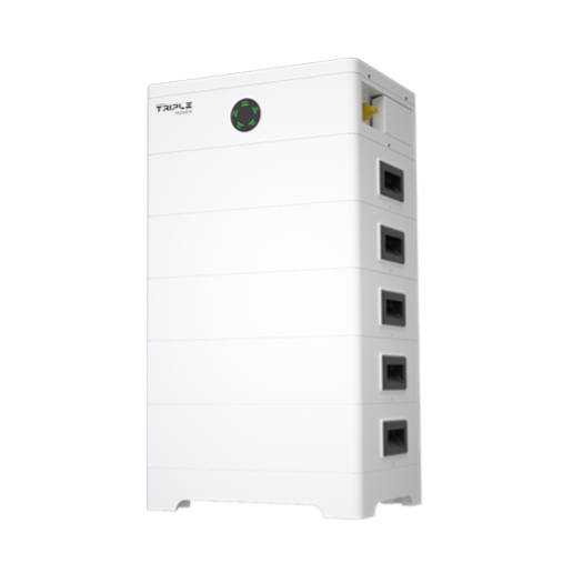
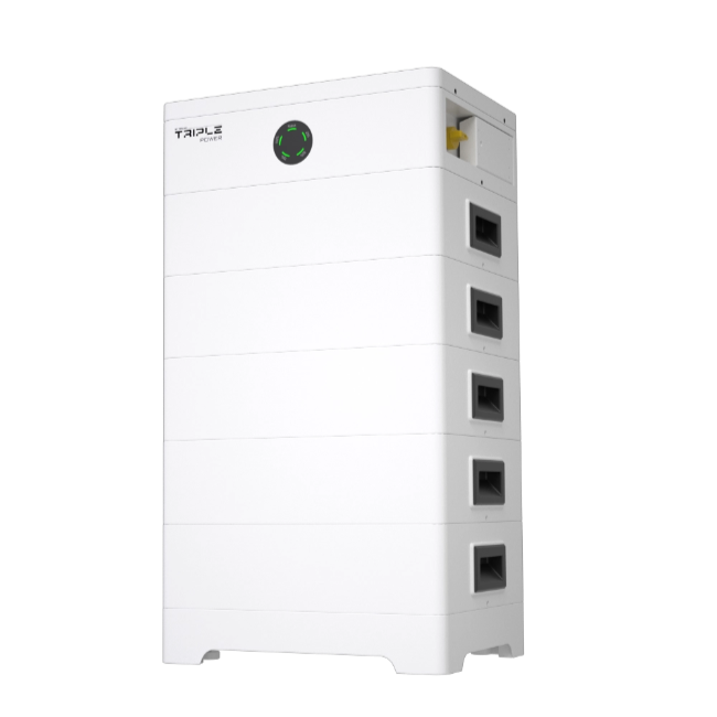
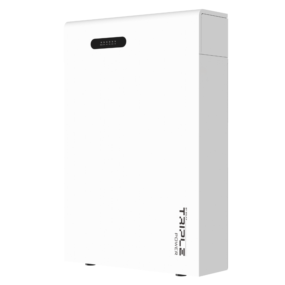
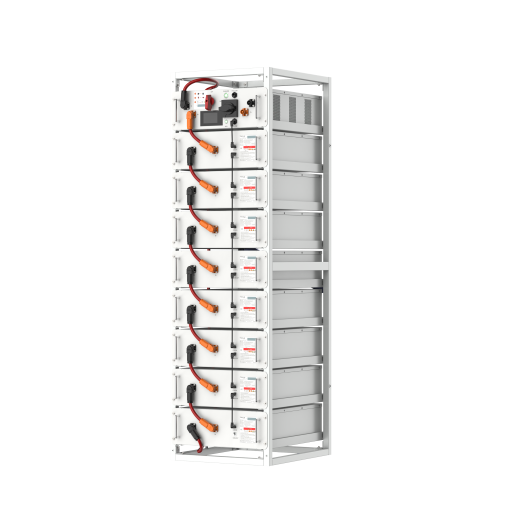
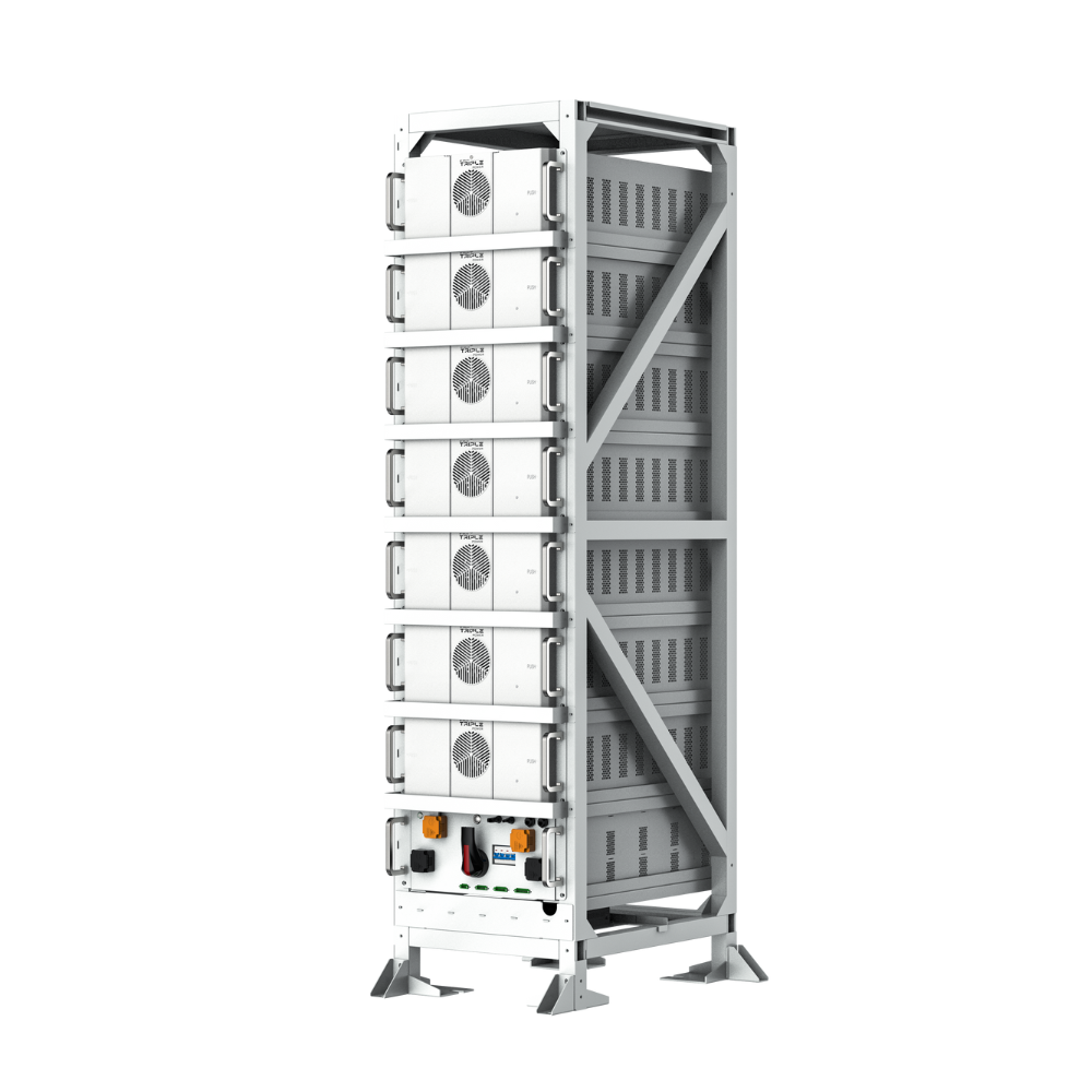
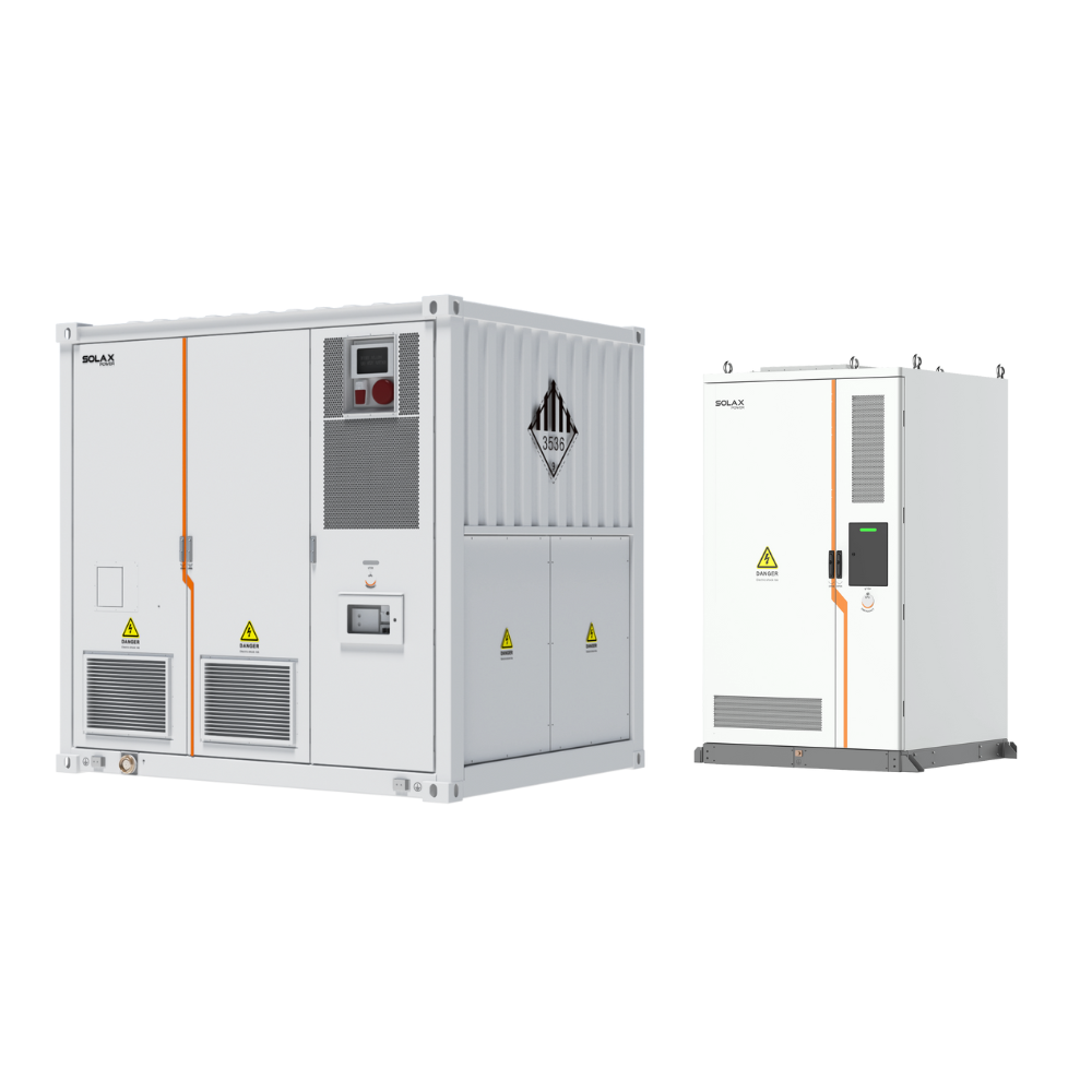
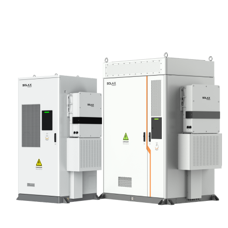
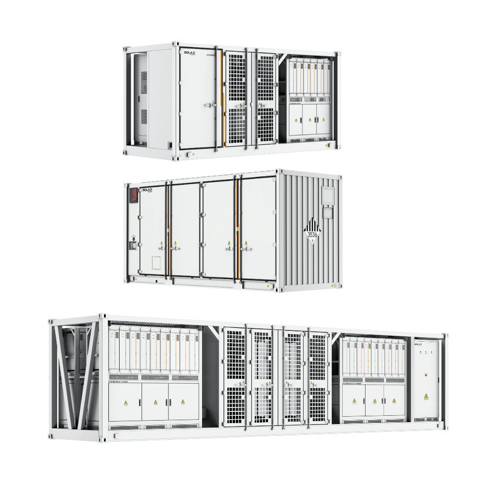
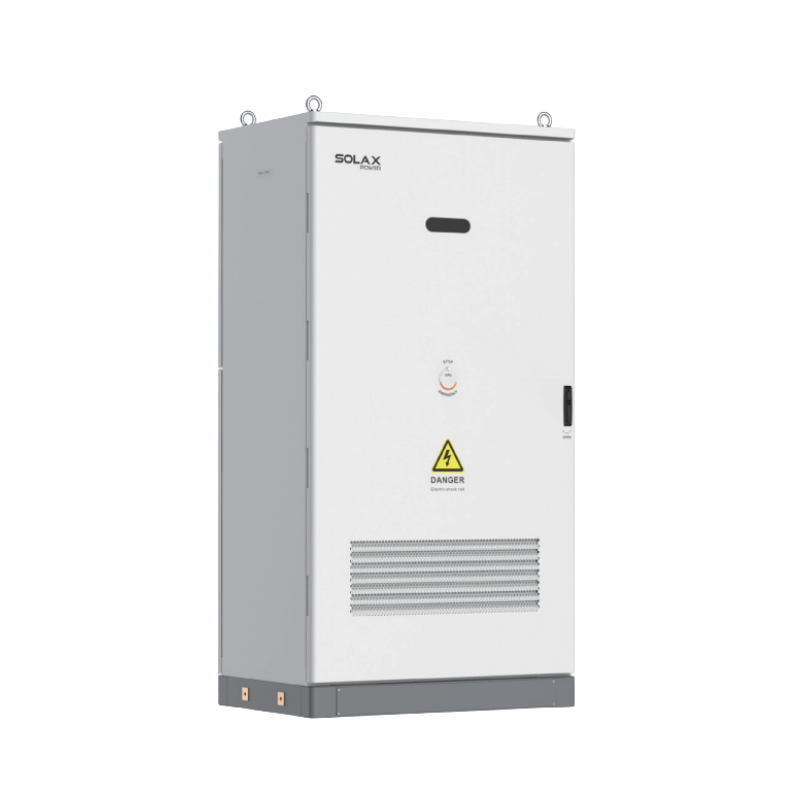
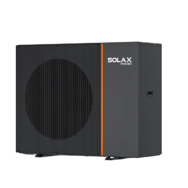
Step 2: Select a TRENE liquid ESS configuration and site layout
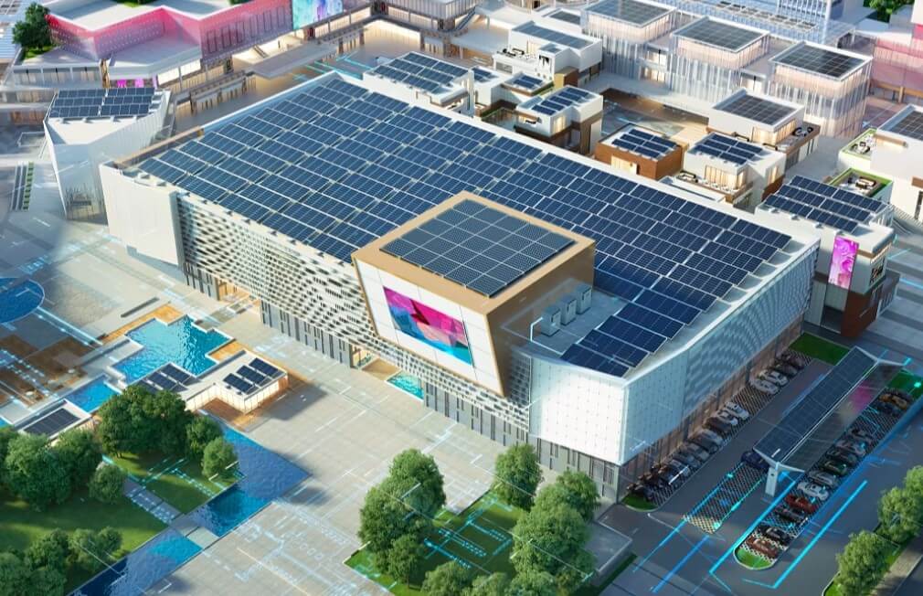
Once your load and autonomy targets are defined, map them to a containerized storage approach and physical layout. Confirm the installation environment: available pad area, access for maintenance, crane/forklift constraints, and separation distances to buildings and egress routes. Then decide where the ESS should sit relative to the transformer, switchgear, and any PV or generator interconnect.
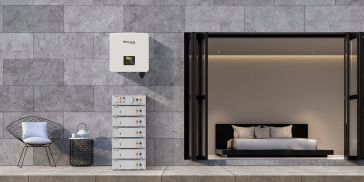
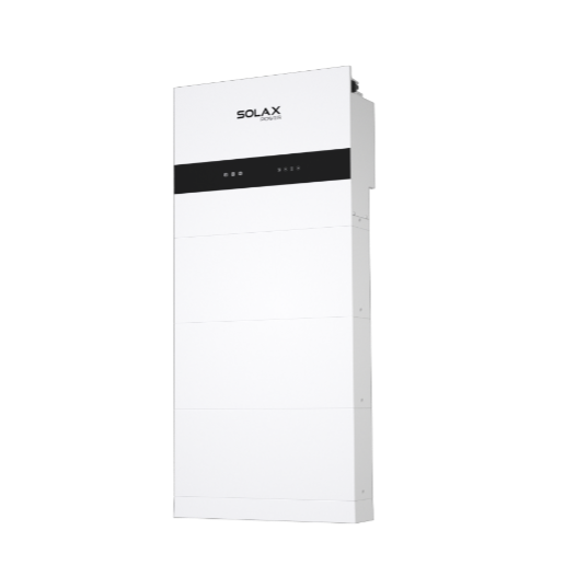
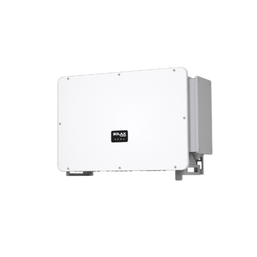
SolaX Power’s ESS TRENE is positioned as a liquid-cooled, C&I-focused energy storage solution intended for stable thermal management and consistent operation. When you’re laying out the site, plan for clear airflow paths around auxiliary components, safe routing for power and communications, and service access to the container doors/panels. Also reserve space for safety signage, emergency shutoff access, and any required bollards or barriers.
To make the configuration selection practical, align these factors: - Peak critical kW vs. inverter/PCS capability (avoid operating continuously at the ceiling). - Required kWh vs. usable capacity (plan headroom for aging, temperature, and reserve SOC). - Duty cycle (daily peak shaving + backup events) vs. expected thermal load. - Monitoring and controls integration needs (SCADA/BMS, alarms, remote O&M).
This is where the ESS TRENE platform’s liquid cooling becomes a planning tool: it can support tighter thermal control in a container footprint, which helps sites that see frequent cycling or high ambient temperatures maintain more consistent output.
Step 3: Configure operating modes for resilience first
After the system is physically planned, define how it will behave day-to-day and during a grid event. A common mistake is to optimize purely for economics (maximum peak shaving) and accidentally leave insufficient energy for outages. Instead, set an explicit backup reserve using a minimum state-of-charge (SOC) threshold that the system should not cross during normal optimization.
Use a layered strategy: 1. Normal mode (grid-connected): peak shaving, TOU arbitrage, PV self-consumption, demand charge management. 2. Standby reserve: maintain a minimum SOC (often 20–40% depending on risk tolerance and autonomy requirements). 3. Backup mode (grid event): isolate critical loads (via ATS/microgrid controller or site switchgear logic), enforce discharge limits, and manage restart sequencing.
If your site has PV, decide whether you want PV to continue producing during islanded operation (requires appropriate controls and anti-islanding compliant microgrid operation). If you have a generator, define whether the ESS should “bridge” until genset start and then switch to generator support while using storage to smooth transients.
Liquid cooling—your TRENE liquid focus—supports reliability here because thermal stability can help reduce abrupt derating during sustained discharge. That said, you still need to configure sensible power limits and SOC floors to match your site’s electrical and safety design.
Step 4: Commission monitoring, alarms, and remote control workflows
A resilient backup-power plan fails if you can’t see what’s happening in real time. During commissioning, validate that monitoring and alarms work end-to-end: from sensors and the BMS/EMS layer, through your site network, to the dashboard and alerting destination used by operators.
Build a monitoring checklist that includes: - SOC, charge/discharge power, and energy throughput trends. - Cooling system health indicators (coolant temperature, pump status, thermal alarms). - Electrical protections (over/under voltage, frequency excursions, insulation monitoring if present). - Event logs for grid loss, transfer actions, and fault history. - Communications status (heartbeat, latency, data gaps) to ensure you’re not “blind” during an incident.
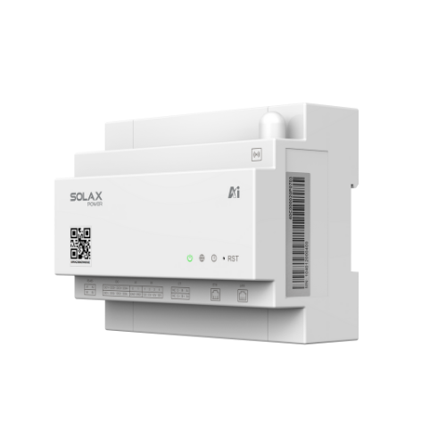
SolaX Power’s ecosystem includes cloud monitoring and energy management capabilities (SolaXCloud) that are designed for real-time visibility and optimization across assets. For a commercial site, define roles and responsibilities: who receives alarms after hours, how fast escalation occurs, and what actions are allowed remotely versus on-site only.
Operationally, add a monthly “monitoring drill”: confirm that alarms trigger, notifications arrive, and the on-call team can pull current status in under five minutes. That drill reduces response time during real outages.
Step 5: Validate backup performance with a controlled grid-loss test
A plan is only as strong as the last successful test. After commissioning, perform a controlled backup-power validation in coordination with your electrical contractor and site safety lead. The test should simulate a grid loss and verify that critical loads remain stable, transfer logic works, and the ESS returns to normal operation safely afterward.
Use a staged approach: 1. Pre-test readiness: confirm SOC above your test threshold, no active alarms, and that emergency stop access is clear. 2. Islanding/transfer test: simulate grid loss, confirm critical-load bus remains within acceptable voltage/frequency limits, and document transfer time. 3. Sustained run: hold operation for a defined duration (e.g., 15–60 minutes) to check thermal and power stability. 4. Restart sequencing: bring back loads in planned order to prevent inrush spikes and nuisance trips. 5. Return-to-grid: confirm synchronization/transfer back logic and verify the system resumes normal reserve management.
During the sustained run, pay attention to thermal behavior—this is where TRENE liquid cooling should demonstrate its value through stable temperatures and consistent output. Log key parameters and keep the report as part of your compliance and resilience documentation.
For general electrical safety expectations in industrial environments, OSHA emphasizes protecting employees from electrical hazards through safe work practices and appropriate controls (osha.gov). Use that guidance to structure who can operate switchgear, what PPE is required, and how lockout/tagout is applied during test events.
TRENE liquid Backup Power in Different Scenarios
- High-heat sites (hot climates or rooftop-adjacent yards): Increase your reserve SOC slightly and schedule heavier cycling during cooler hours when possible. Validate that coolant and container thermal alarms remain well below thresholds during peak ambient. In these environments, TRENE liquid cooling is often chosen to reduce temperature swings that can trigger derating.
- Sites with frequent short outages (seconds to minutes): Prioritize fast detection and transfer logic, and configure the ESS to handle repeated shallow discharge events without draining reserve. Test multiple “blips” back-to-back so you can verify the system doesn’t latch into a fault state after the third or fourth event.
- PV-heavy sites (midday surplus, evening peaks): Use storage to capture midday overproduction while maintaining a backup reserve floor. If islanding with PV is required, confirm the control scheme supports stable microgrid operation and does not trip on voltage/frequency excursions when clouds pass.
- Process loads with large inrush (motors, compressors): Implement staged restart and consider limiting instantaneous discharge power to reduce stress on electrical components. Validate that the ESS can support motor starts without voltage sag that could trip drives or PLC power supplies.
Prerequisites & Safety
Required Tools & Materials
To execute a reliable backup-power setup around ESS TRENE and TRENE liquid cooling, prepare these basics before commissioning and testing: - Single-line diagram and load list with verified kW/kWh and critical-load boundaries. - Network plan (IP ranges, firewall rules, VLANs if used) for monitoring connectivity. - Commissioning checklist covering alarms, protections, and mode settings. - Calibrated electrical test tools appropriate for your gear (and rated for the environment). - Thermal/operations logging method (dashboard export, SCADA historian, or test sheets). - Site operating procedure (SOP) for grid-loss tests, including roles and stop conditions.
Safety Considerations
Energy storage systems combine high energy density with electrical and thermal risks, so treat safety as part of performance. Apply these practices: - Lockout/tagout (LOTO) discipline: Ensure only authorized personnel operate switchgear and isolation devices during testing, and document LOTO boundaries. - Clear emergency access: Keep paths to emergency stop and disconnect points unobstructed and labeled. Train staff on when to use them and what happens afterward. - Battery and cooling alarms are stop signs: If you see thermal, coolant, insulation, or overcurrent alarms, stop the test and investigate rather than “pushing through.” - PPE and approach boundaries: Use PPE appropriate to arc-flash and electrical hazard analysis, and enforce approach limits around energized gear. - Post-event inspection: After any outage or test, inspect logs for warnings that did not become full alarms—those are often early indicators of future failures.
Troubleshooting
| Problem | Cause | Fix |
| Backup runtime is shorter than expected | Reserve SOC set too low, critical loads higher than the load list, or power limits causing early shutdown | Re-measure critical loads at the main and critical-load panels, raise minimum SOC reserve, and repeat the grid-loss test with a sustained run and logged kW/kWh. |
| System derates during sustained discharge | High ambient temperature, cooling loop issue, or conservative thermal limits | Check coolant temperature trends, verify pump/fan operation, clean/clear container ventilation paths, and adjust discharge power limits to keep temperatures stable. |
| Nuisance trips during transfer to backup | Inrush currents, poor restart sequencing, or protection settings not aligned with load behavior | Implement staged restart (largest motors last), add soft-start/VFD settings where possible, and coordinate protection settings with the electrical engineer. |
| Monitoring shows data gaps during events | Network instability, firewall rules, or insufficient local buffering | Validate wired connectivity, whitelist required ports/addresses, and ensure local event logging continues even if cloud connectivity drops. |
| SOC does not recover after an outage | Control mode still in backup state, PV/generator coordination issue, or charge limits too strict | Confirm return-to-grid state machine, verify charging permissions and limits, and review whether reserve logic prevents charging above the threshold. |
FAQ
A: Start by calculating the kWh needed for your minimum autonomy target (for example, 2 hours at your measured critical-load kW). Then set the reserve SOC so that usable energy above that floor covers the target plus a buffer for cold/hot derating and battery aging. Many commercial sites begin with a 20–40% reserve and refine it after real tests. After the first controlled outage simulation, adjust the reserve to match actual load behavior instead of estimates.
A: Stop the test, stabilize the site (either return to grid or shut down per SOP), and capture the full event log and time stamps. Next, confirm whether the alarm is thermal, electrical protection, communications, or mode/logic related, because the corrective actions differ. Only restart testing after the root cause is identified and a corrective change is made (settings, wiring, load sequencing, or cooling inspection). Treat repeat alarms as a sign to re-check assumptions in your load list and transfer design.
A: Yes, but you must explicitly prioritize backup by maintaining a reserve SOC and enforcing it during economic optimization. Configure operating logic so peak shaving cannot drain the reserve below your minimum autonomy requirement. Also, confirm that your demand-management strategy doesn’t schedule aggressive discharge right before your site’s highest outage risk window. The safest approach is to test the strategy under realistic weekday peaks and then repeat a grid-loss test without changing settings.
A: Use staged restart so the biggest inrush loads come back last, and add delays between load groups (often 5–30 seconds depending on the process). If you have VFDs, tune acceleration ramps and current limits so starts are smoother. Verify that protection settings coordinate with the temporary inrush profile instead of tripping immediately. Finally, confirm that voltage sag on the critical-load bus stays within the tolerance of PLC power supplies and motor control circuits during starts.
A: Tie checks to both calendar time and operational cycles, because frequent cycling stresses thermal systems more than standby use. Review temperature trends and cooling alarms at least monthly, and do a deeper inspection after any prolonged discharge event or heat wave. Include verification of pump status, coolant temperature stability, and any filters or airflow paths that support auxiliary cooling components. If you notice rising temperatures at the same discharge power over time, treat it as an early signal to inspect before it becomes a derating or shutdown issue.
Conclusion
Securing commercial backup power is mainly about discipline: define critical loads, choose a realistic autonomy target, configure modes that protect reserve energy, and validate performance with controlled testing. With a liquid-cooled approach like ESS TRENE using TRENE liquid thermal management, you can build a more predictable resilience strategy for high-duty or high-heat environments—provided monitoring, safety workflows, and commissioning checks are done thoroughly.
If you’re planning a containerized backup-power deployment, review the C&I solution details and align them to your site’s operating modes and test plan: https://www.solaxpower.com/commercial-industrial-solutions.html